What is UART and Why It Matters in Embedded Systems
UART is a key serial communication protocol used in embedded systems and connected devices. It connects hardware components by converting standard data into a serial format and back again.
Thanks to its simplicity and flexibility, UART is widely used in applications like IoT devices, sensors, and GPS modules.
Unlike synchronous protocols, UART works without a shared clock. This design makes it ideal for short to medium-distance communication. It offers a cost-effective and reliable solution for many real-world applications.
UART also requires minimal hardware setup. This makes it useful for early-stage operations, such as accessing interfaces before an operating system boots. For example, engineers often use UART to collect boot logs during network device troubleshooting.
Its versatility makes UART a critical tool for smooth communication and debugging in embedded systems.
Understanding Serial Communication Protocols
Serial communication lets electronic devices share data using just a few wires. Common protocols include UART, SPI, and I2C.
UART is asynchronous. It works well for point-to-point communication, such as between a microcontroller and a sensor or a serial port.
SPI offers synchronous communication with fast data transfer. Developers often use it to connect high-speed peripherals like sensors and memory chips.
I2C is also synchronous but supports multiple devices on the same bus. It’s ideal for applications that require several components to communicate, like real-time clocks and environmental sensors.
Each protocol serves different needs. The choice depends on factors like speed, complexity, and how well it fits the devices in your project.
How UART Works: Step-by-Step Process
UART (Universal Asynchronous Receiver/Transmitter) converts parallel data from a microcontroller or computer into serial data for transmission—and does the reverse during reception. Here’s how it works:
1. Data Formatting
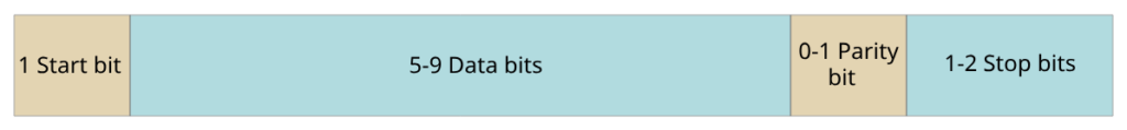
Before transmission, UART formats data into a frame. A typical frame includes a start bit, data bits (usually 8), an optional parity bit, and one or more stop bits. This format keeps both devices in sync.
2. Transmission
When ready to send, the UART starts with a start bit, then sends the data bits, parity bit (if used), and stop bit in order. It sends each bit at a defined baud rate, which controls the speed of transmission.
3. Reception
The receiver constantly checks the communication line for a start bit. Once detected, it reads the incoming bits until it reaches the stop bit, forming a full data frame.
4. Buffering
The receiver stores incoming data in a buffer. This allows the main processor to read the data later, preventing loss if it’s busy with other tasks.
5. Error Detection
UART supports parity checking to detect transmission errors. If it finds an error, the system can trigger error-handling routines to respond accordingly.
UART Basics: Transmitting and Receiving Data
UART uses start and stop bits to mark the beginning and end of each data frame. These bits help ensure accurate communication between devices.
Start Bit
The start bit tells the receiver that a data frame is starting. It changes the signal from high (logic high) to low (logic low). This shift helps the receiving device sync with the incoming data stream.
Stop Bit
The stop bit marks the end of the frame. After this bit, the line returns to its idle state (logic high). If the receiver doesn’t detect the stop bit correctly, it may signal a transmission error. Stop bits also give the receiver time to prepare for the next frame.
Baud Rate and Its Impact on Data Transmission
Baud rate refers to the number of bits transmitted or received per second. A higher baud rate means faster data transfer, allowing more information to be sent in less time.
However, higher baud rates are more prone to noise and signal degradation. They also reduce the maximum cable length you can use. So, the baud rate must be carefully chosen based on your application’s needs.
Matching Baud Rates
Both devices in UART communication must use the same baud rate. Since UART doesn’t share a clock, mismatched baud rates will lead to data errors or loss.
Choosing the Right Baud Rate
When selecting a baud rate, consider:
- The type and size of data
- Noise in the environment
- Distance between devices
You might need to test different baud rates to find the best one for your setup. Common standard baud rates include 2400, 4800, 9600, 19200, 38400, and 115200 bps.
To support high baud rates, the CPU clock speed must be fast enough to keep up with the transmission rate.
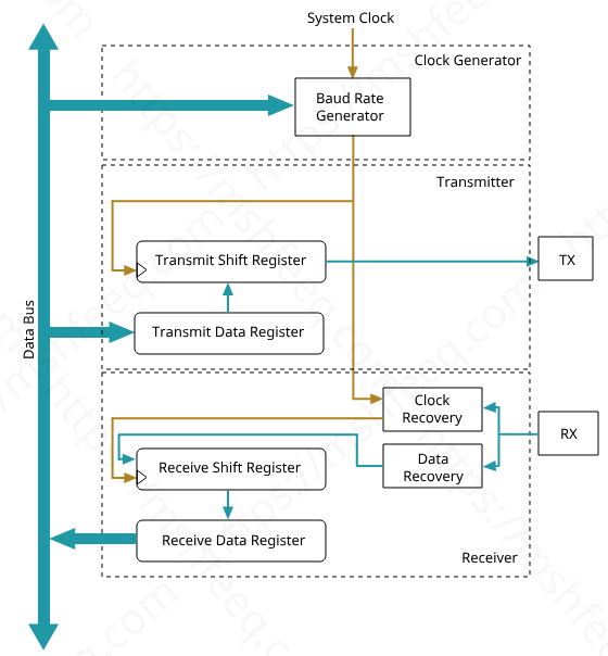
UART Hardware Implementation
UART communication depends on two main hardware components: the transmitter and the receiver. These work together to convert and interpret data across serial communication lines.
UART Transmitter
The UART transmitter takes parallel data from a microcontroller and converts it into serial format for transmission. It structures the data into frames that include:
- A start bit
- Data bits (usually 8)
- An optional parity bit for error checking
- One or more stop bits
This framing helps the receiver stay in sync and understand when each data packet begins and ends.
The data is written into a serial out shift register, which pushes the bits out one at a time. This happens at the configured baud rate, controlling the speed of transmission.
UART Receiver
The UART receiver takes the incoming serial data and converts it back into parallel format for use by the microcontroller or other components. It watches the signal line to detect the start bit, then captures the data, checks the parity (if used), and ends with the stop bit.
Received data is stored temporarily in a buffer. This prevents data loss when the microcontroller is busy and cannot immediately process incoming data.
The receiver may also include error detection, like parity checking, which flags transmission issues. This boosts reliability and helps with error handling during communication.
UART Pin Functions Explained: TX, RX, RTS, CTS, and More
UART communication uses specific pins to manage data transmission between devices. Each pin has a distinct role that ensures smooth and reliable data flow.
TX (Transmit)
The TX pin sends data from the UART transmitter (such as a microcontroller) to a receiver. When the device is ready to send data, it pushes the data out bit by bit through the TX pin.
Important: The TX pin of one device should connect to the RX pin of the other.
RX (Receive)
The RX pin receives incoming serial data from the other device. The UART receiver reads the data coming through this pin and passes it to the microcontroller or system for processing.
Connection Tip: Connect the RX pin of your device to the TX pin of the other device.
RTS (Request to Send)
RTS is an optional hardware flow control signal. When the transmitting device is ready to send data, it sets the RTS line to inform the receiving device. This helps prevent data loss when the receiver is not ready to handle new data.
CTS (Clear to Send)
CTS is the counterpart to RTS. It is used by the receiving device to indicate that it can accept data. The transmitter waits for this signal before starting transmission, ensuring safe and controlled data flow.
DTR (Data Terminal Ready)
DTR is another optional control pin. It signals that a data terminal equipment (DTE)—like a computer or microcontroller—is ready to start communication. This pin is often controlled by software or system settings.
DSR (Data Set Ready)
DSR works alongside DTR. It’s used by data communication equipment (DCE)—such as a modem or communication module—to inform the DTE that it’s ready to communicate. Once DSR is active, data exchange can begin.
UART vs USART: Key Differences Explained
When working with embedded systems, choosing between UART and USART depends on your communication needs. Here’s a clear comparison between the two:
| Feature | UART | USART |
|---|---|---|
| Full Form | Universal Asynchronous Receiver/Transmitter | Universal Synchronous/Asynchronous Receiver/Transmitter |
| Communication Mode | Works only in asynchronous mode | Supports both synchronous and asynchronous modes |
| Clock Usage | No clock line; relies on start and stop bits for timing | Uses a shared clock signal for synchronization in synchronous mode |
| Clock Source | Baud rate generated using a fixed or programmable divisor of the system clock | Offers more precise baud rate control, using internal or external clock sources |
| Data Framing | Includes start bit, data bits, optional parity bit, and stop bit | Framing depends on mode and configuration; may vary |
| Error Handling | Supports error detection with parity checking | Supports both error detection and correction (e.g., checksum, CRC) |
| Typical Use Cases | Used in simple asynchronous communications: serial ports, sensors, GPS modules | Preferred for advanced use cases requiring clock sync, high precision, or robust error control |
Practical Examples of UART Communication in Embedded Systems
One practical example of UART communication in embedded systems is its implementation on the ATtiny85 microcontroller using the Universal Serial Interface (USI). We’ve created a detailed guide that walks you through the process step by step. This hands-on example not only reinforces how UART works but also highlights how to use USI to emulate UART on microcontrollers without built-in UART hardware.
Check out the full post for deeper insights and a practical walkthrough to strengthen your understanding of UART in real-world embedded applications.
Pingback: USI UART Data Transmission: A Complete How-To Guide
Pingback: USI UART Receive with ATtiny85 – Embedded UART Tutorial