Introduction: Exploring GPIO and Charlieplexing
In this blog series, we’ll dive into General Purpose Input/Output (GPIO) and the fascinating concept of Charlieplexing. If you’re eager to learn how to control multiple LEDs with just a few GPIO pins, you’ve come to the right place.
I was inspired to explore this topic after reading an insightful article on this link, which led me to discover the efficiency of Charlieplexing.
Why GPIO and Charlieplexing Matter
GPIO pins are essential for interacting with the physical world through digital signals.
Charlieplexing is a brilliant technique for driving multiple LEDs using fewer pins. By leveraging the bidirectional nature of GPIOs, you can create complex LED displays and lighting effects without the need for extra components. This showcases the power of efficient problem-solving in electronics.
What to Expect in This Series
In this series, we’ll walk you through everything you need to know about GPIOs and Charlieplexing. While we’ll briefly cover the basics of GPIO, our main focus will be on understanding Charlieplexing. You’ll quickly learn how this technique works and its many applications.
Although this post offers a quick overview of GPIO, it’s a vast topic. We recommend exploring further if you want a deeper understanding. Let’s start with the essential concepts that will lay the foundation for Charlieplexing.
What is General Purpose Input/Output (GPIO)?
GPIO pins are versatile components found on microcontrollers and single-board computers. These pins allow you to interface with external devices.
- Input: GPIO pins can detect signals like button presses or sensor data by measuring voltage levels. They have two states: high (logic 1) and low (logic 0).
- Output: GPIO pins can also drive devices such as LEDs, motors, and relays. They have two states: high (logic 1) and low (logic 0).
- Tristate: Some GPIO pins can enter a third state, called tristate. In this mode, the pin disconnects from the circuit, making it high impedance. It’s often used when multiple devices share a bus.
For a deeper dive into pin configurations, check out our post: Exploring Pin Configurations in Microcontrollers.
How Charlieplexing Works
Charlieplexing is an efficient method for driving multiple LEDs using fewer GPIO pins. Unlike traditional multiplexing, which requires one pin per LED, Charlieplexing uses GPIOs’ bidirectional capabilities to reduce the number of required pins.
Here’s how it works:
- LEDs are arranged between pairs of GPIO pins, each in the opposite direction.
- By selectively enabling different combinations of pins, you can light up specific LEDs.
Simple Example with Two GPIO Pins
Let’s start with a simple example using two GPIO pins connected to two LEDs:
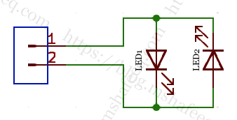
GPIO Pin 1: Set as output, driven high (logic 1)
GPIO Pin 2: Set as output, driven low (logic 0)
This configuration will light up LED1. To light LED2, you reverse the pin settings:
GPIO Pin 1: Set as output, driven low (logic 0)
GPIO Pin 2: Set as output, driven high (logic 1)
Expanding to More GPIO Pins
Now, let’s expand the idea with three GPIO pins. The setup would look like this for LED1:
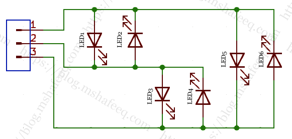
- GPIO 1: Logic 1
- GPIO 2: Logic 0
- GPIO 3: High impedance (disconnected)
You can extend this concept to control more LEDs using additional GPIO pins. The circuit will remain simple, and you can create impressive LED displays with minimal wiring.
Sample Project: Charlieplexing with 3 Pins
In this sample project, we’ll use three GPIO pins to create an LED pattern. Each light turns on briefly, one after the other, forming a continuous pattern. The ATtiny85 chip ensures all LEDs shine with the same brightness.
Project Features:
- A button (sw1) to switch between six different light patterns
- An adjustable speed using preset RV1
The LEDs light up in a continuous sequence due to the human eye’s afterimage effect.
Code and Demo
You can find the code for this project on my GitHub page. Additionally, check out the demonstration video to see the project in action.