In the ADC Polling method, I have covered the basics about the ADC. If you haven’t checked it, I strongly recommend reviewing that post before starting this one. In this post we are directly jumping to the ADC interrupt.
Exercise
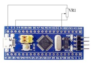
Write a program to blink LED (ON time 50ms) using a single channel. The delay between the two flash should be able to control using a preset connected into any one of the ADC input channel. This should be implemented using interrupt in single conversion mode. Here is the hardware setup

Registers used
- APB2 peripheral clock enable register (RCC_APB2ENR) – Enable clock for ADC and GPIO port A and C
- Port configuration register high for port C (GPIOC_CRH) – Enable GPIO port C output for built-in LED
- Port configuration register high for port A (GPIOA_CRL) – Enable the analog input channels
- ADC Control Register 1 (ADC_CR1) – ADC interrupt enable.
- ADC Control Register 2 (ADC_CR2) – ADC enable and calibration.
- ADC Regular Sequence Register 3 (ADC_SQR3) – Specify the channels to be converted
- ADC Status Register (ADC_SR) – Check if the conversion completed or not
- ADC Data Register (ADC_DR) – Get the converted data.
Solution
The ADC setup is the same as in the polling method, except for an additional step to enable the interrupt. To enable the interrupt, first select the channel in the last sequence of ADC_SQR3. Then set the EOCIE bit of ADC_CR1. Configure the NVIC to process the ADC Interrupt Request (ADC1_2_IRQn) when the interrupt is occured.
// Select first channel
ADC1->SQR3 = 1;

// Enable end of conversion interrupt
__disable_irq();
ADC1->CR1 |= ADC_CR1_EOCIE;
NVIC_EnableIRQ(ADC1_2_IRQn);
__enable_irq();
From the ISR, multiply the ADC value with some constant to get a lower value. I am taking the constant value as 60/3600 where the 3600 is the maximum ADC value (refer the ADC polling method). This value will adjust the maximum value from 0 to 60.
void ADC1_2_IRQHandler() {
    uint16_t adcDelay = ADC1->DR;
    loopCount = adcDelay * 60 / 3500;
}
Clear the EOC flag in the ADC status register ADC_SR. Now loop until the loopCount and give a delay of 50ms inside the loop. Turn LED ON when the count is 0 and turn OFF when the count is 1. Enable the ADC after 50ms for every interrupt.
for(int i = 0; i < loopCount; i++) {
    if(i < 2) {
        TOGGLE_LED();
    }

    delay(50);
    ADC1->CR2 |= ADC_CR2_ADON;
}
When the preset is at minimum, the loop count will be 0 or 1. In such cases, we will need to enable the ADC explicitly since the code inside the loop will not work.
// if the above loop not executed (when loopCount is 0), the
// conversion won't start. So start the conversion explicitly
if(loopCount <= 1) {
    ADC1->CR2 |= ADC_CR2_ADON;
}
Congratulations, you have done. Combining all together, the code would be like
void ADC1_2_IRQHandler() {
    uint16_t adcDelay = ADC1->DR;
    loopCount = adcDelay * 60 / 3500;
}

int main(void)
{
    // Enable clock for GPIOA, GPIOC & ADC1 peripheral
    RCC->APB2ENR |= RCC_APB2ENR_IOPCEN;
    RCC->APB2ENR |= RCC_APB2ENR_IOPAEN;
    RCC->APB2ENR |= RCC_APB2ENR_ADC1EN;

    // Configure built in LED as output
    GPIOC->CRH &= ~(GPIO_CRH_CNF13 | GPIO_CRH_MODE13);
    GPIOC->CRH |= GPIO_CRH_MODE13_0;

    // GPIOA1 analog input mode
    GPIOA->CRL &= ~(GPIO_CRL_CNF1 | GPIO_CRL_MODE1);
    GPIOA->CRL &= ~(GPIO_CRL_CNF2 | GPIO_CRL_MODE2);

    // Document RM0008 Section 11.3.1
    // The ADC can be powered-on by setting the ADON bit in the
    // ADC_CR2 register. When the ADON bit is set for the first
    // time, it wakes up the ADC from Power Down mode. Conversion
    // starts when ADON bit is set for a second time by software
    // after ADC power-up time (giving ~100ms)
    ADC1->CR2 |= ADC_CR2_ADON;
    delay(100);
    ADC1->CR2 |= ADC_CR2_ADON;

    // Caliberate ADC after each power up
    ADC1->CR2 |= ADC_CR2_CAL;
    while(ADC1->CR2 & ADC_CR2_CAL);

    // Select first channel
    ADC1->SQR3 = 1;

    // Enable end of conversion interrupt
    __disable_irq();
    ADC1->CR1 |= ADC_CR1_EOCIE;
    NVIC_EnableIRQ(ADC1_2_IRQn);
    __enable_irq();

    // Turn LED off
    // TOGGLE_LED();

    while (1) {
        ADC1->SR &= ~(ADC_SR_EOC);
        for(int i = 0; i < loopCount; i++) {
            if(i < 2) {
                TOGGLE_LED();
            }

            delay(50);
            ADC1->CR2 |= ADC_CR2_ADON;
        }

        // if the above loop not executed (when loopCount is 0), the
        // conversion won't start. So start the conversion explicitly
        if(loopCount <= 1) {
            ADC1->CR2 |= ADC_CR2_ADON;
        }
    }
}
Full source code available in the github repository.
Here is the video of my attempt.