In our previous post, I explained how to configure the GPIO of STM32F103C6T6. I covered some basics in that post. So, before going through this post, I strongly recommend taking a look at my previous post, STM32F103C6T6A Bare Metal Programming – GPIO.
The EXTI (External Interrupt) is a peripheral used to handle external interrupts triggered by external events, such as a button press or a signal change on a pin. The EXTI peripheral allows you to configure specific GPIO pins to trigger interrupts when certain events occur, such as a rising or falling edge, or both. This enables you to respond to external events without continuously polling the GPIO pins, which can save power and CPU resources.
The NVIC (Nested Vector Interrupt Controller) is not a peripheral itself but rather a core component of the ARM Cortex-M3 processor architecture used in STM32 microcontrollers. It resides inside the STM32 processor and is responsible for managing and prioritizing interrupt requests from various peripherals, including EXTI.
When an external event occurs on a configured pin, the EXTI peripheral signals the NVIC by generating an interrupt request. The NVIC then prioritizes and manages these interrupt requests and, based on their priority, can trigger the corresponding interrupt service routine (ISR) in your application code.
If you are a beginner, you cannot find much information regarding the EXTI in the datasheet. The section 10 of the reference manual explains about the external interrupts.
In the provided assembly code (startup_stm32f103x6.s), all possible Interrupt Service Routines (ISRs) are already declared. The assembly code is structured such that if there is a specific ISR definition, that ISR will be called when the corresponding interrupt occurs. However, if an ISR is not explicitly defined, the default ISR handler (Default_Handler) will be called instead. This setup ensures that all interrupts are handled appropriately, either by specific ISRs or by the default handler.
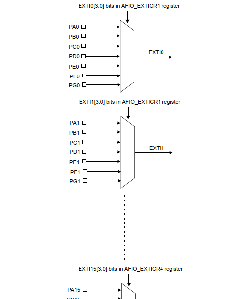
In STM32 microcontrollers, there are 16 External Interrupt Lines (EXTI0-EXTI15) that are connected to the NVIC. GPIO pins are multiplexed to these EXTI lines, allowing any GPIO pin to trigger an external interrupt by configuring the appropriate registers. This flexibility enables developers to use GPIO pins to respond to external events efficiently, enhancing the versatility of the microcontroller in various applications.
Registers Used
- APB2 peripheral clock enable register (RCC_APB2ENR) – Used to enable clock to the GPIO peripheral
- Port Configuration Register Low (GPIOx_CRL) – Configure the GPIO pin from 0 to 7
- Port Configuration Register High (GPIOx_CRH) – Configure the GPIO pin from 8 to 15
- Port Output Data Register (GPIOx_ODR) – Configure the output data (0 or 1) when the pin is configured as output and pull-up/pull-down when pin is configured as input
- External Interrupt Configuration Register 1 (AFIO_EXTICR1) – To tie a particular pin to the interrupt line.
- Falling Trigger Selection Register (EXTI_FTSR) – Configure falling edge as trigger of interrupt
- Raising Trigger Selection Register (EXTI_RTSR) – Configure raising edge as trigger of interrupt
- Event Mask Register (EXTI_IMR) – Enable a particular interrupt line.
- Software Interrupt Event Register (EXTI_SWIER) – Trigger interrupt using software
- Pending Register (EXTI_PR) – Flag to show if any unhandled interrupts.
Exercise
Write a program to achieve the same output as the exercise explained in the GPIO post using the interrupt.
Solution
Here the approach we are taking is a bit different. Initially we will configure the interrupt and wait in an infinite loop. The blink LED program will be inside a flag which will be enabled from the ISR.
To use the EXTI functionality on a GPIO pin, such as connecting PB0 to EXTI0, you typically need to enable clocks to the relevant GPIO port (Port B in this case) and the AFIO (Alternate Function Input Output) peripheral. The AFIO peripheral is responsible for managing alternate function assignments for GPIO pins, including EXTI line mapping. Also, we need to enable clock to port C as the LED is connected in this port.
// Enable clock for GPIOB, GPIOC and AFIO peripheral
RCC->APB2ENR |= (RCC_APB2ENR_IOPCEN | RCC_APB2ENR_IOPBEN | RCC_APB2ENR_AFIOEN);
Configure PB0 as input pull-up and PC13 as output as before.
// Configure PC13 pin as output push-pull maximum speed 10MHz
GPIOC->CRH &= ~(GPIO_CRH_CNF13 | GPIO_CRH_MODE13);
GPIOC->CRH |= GPIO_CRH_MODE13_0;

// Configure PB0 pin as input pull up or pull down
GPIOB->CRL &= ~(GPIO_CRL_CNF0 | GPIO_CRL_MODE0);
GPIOB->CRL |= GPIO_CRL_CNF0_1;

// PBO as pull up
GPIOB->ODR |= GPIO_ODR_ODR0;
Now configure the interrupt. For the GPIO exercise, I have explained that the PB0 become logic 0 when the button is pressed. When the button is released, the input state become high. Since we need to blink the LED on releasing the button we can take the low to high (Rising Edge) transition of input as interrupt trigger. The code below is self explanatory.
// Tie EXTI0 with PB0
AFIO->EXTICR[0] &= ~AFIO_EXTICR1_EXTI0;
AFIO->EXTICR[0] |= AFIO_EXTICR1_EXTI0_PB;

// Trigger on rising edge
EXTI->RTSR |= EXTI_RTSR_TR0;

// Enable EXTI0
EXTI->IMR |= EXTI_IMR_MR0;
Clear the interrupt pending flag to ensure no other interrupt is pending.
// Clear the flag
EXTI->PR |= EXTI_PR_PR0;
We have configured the EXTI module and selected the input GPIO. Now we have to configure the NVIC to process the IRQ when the interrupt occurs in EXTI. For this use the NVIC APIs which is defined in Drivers/CMSIS/Include/core_cm3.c/h files. We use the following code to enable EXTI0 line interrupt in the NVIC
// Enable the interrupt line at NVIC
uint32_t prioritygroup = NVIC_GetPriorityGrouping();
NVIC_SetPriority(EXTI0_IRQn, NVIC_EncodePriority(prioritygroup, 10, 0));
NVIC_EnableIRQ(EXTI0_IRQn);
Combining all together.
#include "main.h"

#define TURN_ON_LED()            turn_led_on(TURN_ON)
#define TURN_OFF_LED()           turn_led_on(TURN_OFF)
#define TOGGLE_LED()             turn_led_on(TURN_TOGGLE)

typedef enum {
    TURN_OFF,
    TURN_ON,
    TURN_TOGGLE
} LedState_t;

static int8_t g_handle = 0;
void turn_led_on(LedState_t state);

void delay(uint32_t ms) {
    // Simple delay function (not accurate, just for demonstration)
    for (volatile uint32_t i = 0; i < ms * 1000; ++i) {
        __NOP();  // No operation (compiler barrier)
    }
}
void EXTI0_IRQHandler() {
    EXTI->PR |= EXTI_PR_PR0;
    g_handle = 1;
}

void turn_led_on(LedState_t state) {
    if(state == TURN_TOGGLE){
        GPIOC->ODR ^= GPIO_ODR_ODR13;
    } else if(state == TURN_ON) {
        GPIOC->ODR &= ~(GPIO_ODR_ODR13);
    } else {
        GPIOC->ODR |= GPIO_ODR_ODR13;
    }
}

void setup_exti0_interrupt() {
    // Set PB0 as input
    GPIOB->CRL &= ~GPIO_CRL_MODE0;

    // Configure PB0 as input pull-down/pull-up
    GPIOB->CRL &= ~GPIO_CRL_CNF0;
    GPIOB->CRL |= GPIO_CRL_CNF0_1;

    // Configure PB0 as pull-up
    GPIOB->ODR |= GPIO_ODR_ODR0;

    // Tie EXTI0 with PB0
    AFIO->EXTICR[0] &= ~AFIO_EXTICR1_EXTI0;
    AFIO->EXTICR[0] |= AFIO_EXTICR1_EXTI0_PB;

    // Trigger on falling edge
    EXTI->RTSR |= EXTI_RTSR_TR0;

    // Mask EXTI0
    EXTI->IMR |= EXTI_IMR_MR0;

    // Clear the flag
    EXTI->PR |= EXTI_PR_PR0;

    // Enable the interrupt line at NVIC
    uint32_t prioritygroup = NVIC_GetPriorityGrouping();
    NVIC_SetPriority(EXTI0_IRQn, NVIC_EncodePriority(prioritygroup, 10, 0));
    NVIC_EnableIRQ(EXTI0_IRQn);
}

int main(void)
{
    // Enable clock for GPIOB, GPIOC and AFIO peripheral
    RCC->APB2ENR |= (RCC_APB2ENR_IOPCEN | RCC_APB2ENR_IOPBEN | RCC_APB2ENR_AFIOEN);

    // Configure PC13 pin as output push-pull maximum speed 10MHz
    GPIOC->CRH &= ~(GPIO_CRH_CNF13 | GPIO_CRH_MODE13);
    GPIOC->CRH |= GPIO_CRH_MODE13_0;

    setup_exti0_interrupt();

    TURN_OFF_LED();
    while (1) {
        if(g_handle) {
            for(int i = 0; i < 3; i++) {
                TURN_ON_LED();
                delay(500);
                TURN_OFF_LED();
                delay(500);
            }
            g_handle = 0;
        }
    }
}
Full source code available in the github.