Digital Pin Configurations
Microcontrollers manage digital signals and interface with external devices to ensure efficient and reliable system performance. Understanding these interactions plays a key role in designing effective systems.
Microcontroller I/O (input/output) pins rely on their configuration to determine how they interact with the outside world.
In this article, we will explore three common output configurations: push-pull, open-drain, and tri-state. Each configuration provides unique benefits and suits specific applications.
Engineers and developers working with microcontrollers must understand these configurations. Let’s examine how they function and impact system design and performance.
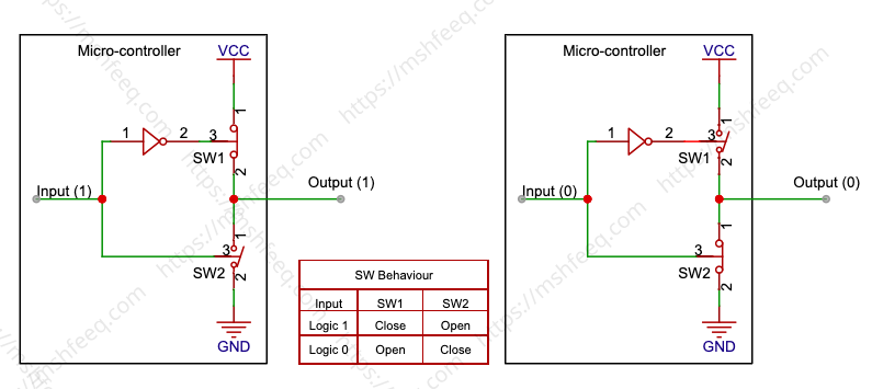
In all the diagrams presented in this article, switches are activated by a signal, with each switch opening when the input signal is high and closing when it is low.
Some Fundamentals
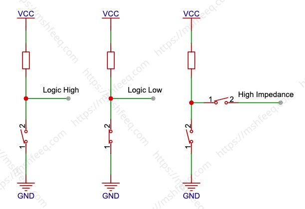
Digital electronics rely on different logic states—low, high, and high-impedance—for effective signal management.
A logic low state, usually close to 0 volts, indicates the absence of a significant signal. In contrast, a logic high state, typically near the supply voltage (Vcc), signifies the presence of a meaningful signal. These states form the foundation of digital communication and computation.
The high-impedance state, also called “tri-state” or “floating” state, disconnects the output from the circuit. This state increases resistance on the signal line, preventing interference and allowing multiple devices to share the same connection.
Push-Pull configuration
A push-pull configuration allows devices to actively drive a signal line both high (logic 1) and low (logic 0). This capability enables them to transmit and receive signals, supporting bidirectional communication.
Think of it as a versatile switch—it can turn a light on and off while also detecting whether the light is already on or off. Digital circuits frequently use this setup to ensure fast and efficient communication between devices.
Push-pull configurations play a crucial role in applications such as LED and motor control. They also appear in digital logic gates, delivering reliable and adaptable performance in electronic systems.
Open drain (Open Collector) Configuration
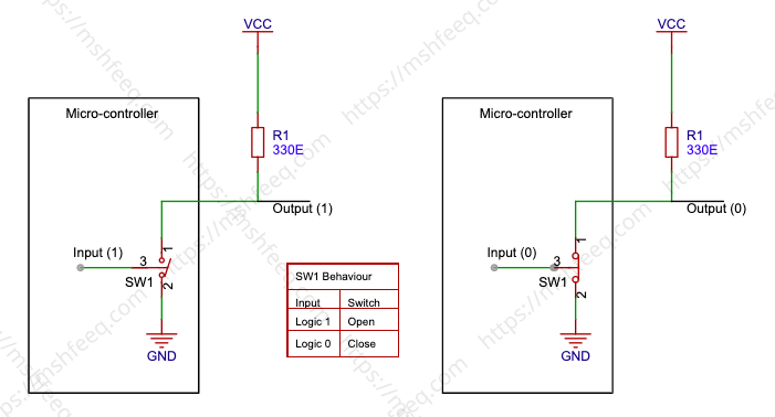
An open-drain configuration allows any device connected to the line to pull the signal to a logic low state (0). However, no device can actively drive the line to a logic high state (1).
When the input pin is set to logic high, the switch remains open, causing the output to enter a floating state. To achieve a logical high state outside the microcontroller, a pull-up resistor is typically used. This resistor connects the signal line to the positive supply voltage, ensuring that the line remains high when no device is pulling it low.
This setup enables seamless communication between devices while maintaining signal integrity. The open-drain configuration with a pull-up resistor is illustrated below (Figure-3).
In an open-drain system, multiple devices can share the same line. Any device can pull the line to logic low when needed, making it useful for wired-AND logic and communication protocols like I²C.
Tri-state configuration
In a tri-state configuration, a pin can operate in three states: high, low, and high-impedance.
When the input signal is high, the pin actively drives the output. Conversely, when the input signal is low, the pin stops driving the output, allowing it to return to its default state.
In the high-impedance state, the pin is effectively disconnected from the circuit, leaving the output free-floating. This tri-state capability is essential for shared bus communication, as it allows multiple devices to take turns using the same signal line without interference. It also enables efficient resource allocation within the microcontroller.
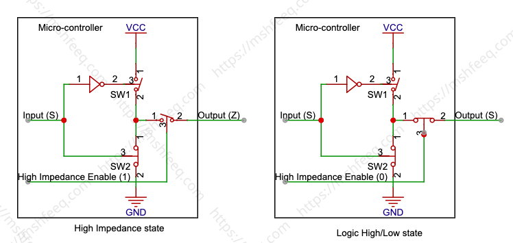
Note: The switches shown in the diagram are for illustrative purposes only; In practical applications, MOSFETs are employed in their place.
Please add your valuable comments here.
Pingback: Learn GPIO and Charlieplexing: Control LEDs with Fewer Pins